 Experiments
Five experiments with the SO-101, from moving the arm by hand to moving it with a webcam. Each one has its code repository, media and an explanation. Build the arm first with the assembly guide.
- TeleoperationA person moves the leader arm; the follower copies it, and everything is recorded.
- ACT policy training with Hugging FaceTeach the arm the task from the recorded demonstrations.
- Forward kinematics with MoveIt and RVizFrom joint angles to where the gripper is, derived by hand and checked against MoveIt.
- Inverse kinematics with obstacle avoidance: sim to realThe gripper loops around and over a cylinder, first on a simulated arm and then on the real one.
- Teleoperation with gesture control using computer visionMove the arm with your hand in front of a webcam.
Experiment 1 of 5
Teleoperation
A person moves the leader arm; the follower copies it, and everything is recorded.
Git repository
- LeRobot (upstream)The library we used:
lerobot-calibrate,lerobot-teleoperateandlerobot-record. - Our changes to LeRobotLink to be added. Rerun 3D robot view, MuJoCo robot and ROS joint-state publisher (see posts 4 to 6).
Videos
Goal
Control the follower arm in real time from the leader arm, and capture the demonstrations that the later experiments learn from.
How it works
The leader and follower are two SO-101 arms with the same six joints. After calibration, both report joint angles in the same units, so LeRobot can read the leader's six angles about 30 times a second and send them straight to the follower as its target positions. No kinematics is needed: it is joint-space copying. Two USB cameras (a fixed top view and one on the wrist) are recorded at the same time.
- Calibrate both arms with
lerobot-calibrateso equal poses give equal readings. - Teleoperate with
lerobot-teleoperate, first without cameras to check the motion, then with the cameras and the Rerun viewer. - Record with
lerobot-record. Each episode stores the six joint positions, the six actions and both video streams, for the task “put the blue box in a bowl”.
In the videos
The first video looks down on the two arms. The operator holds the leader (black) and the follower (red) follows every joint, including the gripper. The second shows the follower lifting a small box while the operator drives it from the leader.
What we added
- A live 3D model of the arm in Rerun while recording (
--display_urdf_path), which makes it easier to judge each demonstration. - Keyboard end-effector teleoperation of a MuJoCo copy of the arm, which is useful when the hardware is not available.
Outcome
We recorded 7 episodes (about 8,700 frames at 30 fps) across our test sessions. That is enough to check that the whole pipeline works from arm to dataset, but it is a small dataset.
Links
- LeRobot: TeleoperateLeader-follower control, with and without cameras.
- LeRobot: Record a datasetHow episodes are captured.
- Our post: Recording datasetsThe exact command and camera setup.
- Our post: Live 3D view in RerunThe
--display_urdf_pathextension.
Experiment 2 of 5
ACT policy training with Hugging Face
Teach the arm the task from the recorded demonstrations.
Git repository
- LeRobot training script
lerobot-train, the script that trains the policy. - Trained model on Hugging FaceLink to be added. The trained ACT model page.
Videos
Photos and diagrams
Goal
Replace the human at the leader arm with a learned policy that performs “put the blue box in a bowl” by itself.
What is ACT?
ACT (Action Chunking with Transformers) is an imitation-learning policy. At each step it looks at the camera images and the arm's joint positions, and predicts a chunk of the next several actions at once instead of a single one. Predicting chunks makes the motion smoother and reduces the compounding of small errors, which is a known problem when a policy is copying demonstrations. It is trained as a conditional variational autoencoder with a transformer, and it is one of the policies that ships with LeRobot.
Pipeline
- Dataset. The teleoperated episodes from Experiment 1, stored in LeRobotDataset format (locally or on the Hugging Face Hub).
- Train. One command; both cameras and the joint state are the inputs, and the six joint targets are the output:
lerobot-train \ --dataset.repo_id=<your-username>/so101_dataset \ --policy.type=act \ --output_dir=outputs/train/act_so101 \ --job_name=act_so101 \ --policy.device=cuda \ --policy.repo_id=<your-username>/act_so101 - Publish. The checkpoint is uploaded to the Hugging Face Hub, so it can be loaded on any machine.
- Deploy.
lerobot-rolloutruns the policy on the follower arm with the same two cameras used for recording.
Why the cameras must match
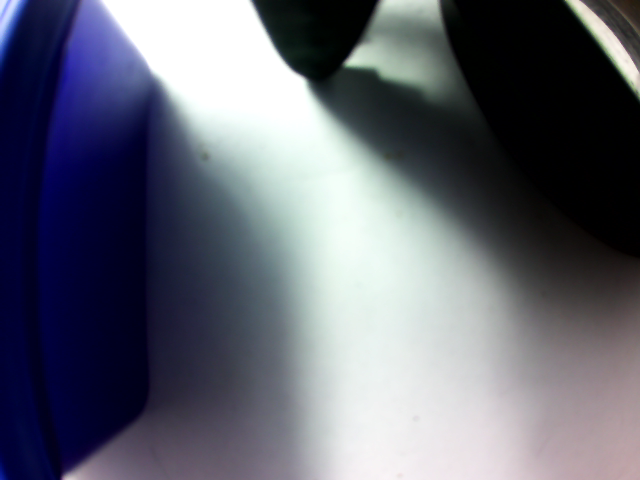
The policy only knows the camera names, resolutions and frame rates it saw in training. At deployment the top and wrist cameras must use the same names and settings as in the recording command, or the model receives inputs it was never trained on.
In the videos
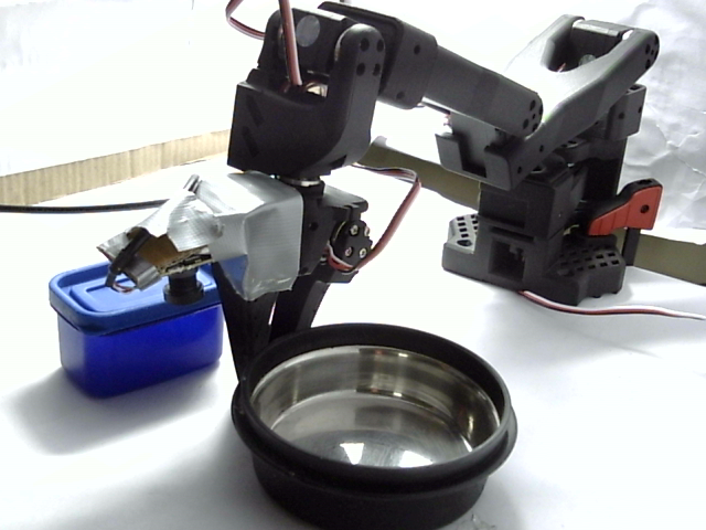
The first video walks through the physical setup: the enclosure with a white backdrop that keeps the scene simple and evenly lit, the arm, the bowl and the box, and the laptop. The second shows the laptop screen during the ACT run, with the camera views and plots visible.
Results
Training curves, the model link and the success rate of the deployed policy will be added here.
Links
- LeRobot: ACTThe policy and its configuration.
- LeRobot: Train a policyThe training command and options.
- LeRobot: Train ACT on Google ColabTraining without a local GPU.
- LeRobot: Run inference and evaluateDeploying the trained policy on the arm.
- ACT paper (Zhao et al., 2023)Learning fine-grained bimanual manipulation with low-cost hardware.
Experiment 3 of 5
Forward kinematics with MoveIt and RViz
From joint angles to where the gripper is, derived by hand and checked against MoveIt.
Git repository
- LerobotFwd_InvKinematicsROS 2 Jazzy workspace: URDF,
ros2_control, MoveIt 2, RViz, the real-hardware bridge and the kinematics documents.
Videos
Photos and diagrams
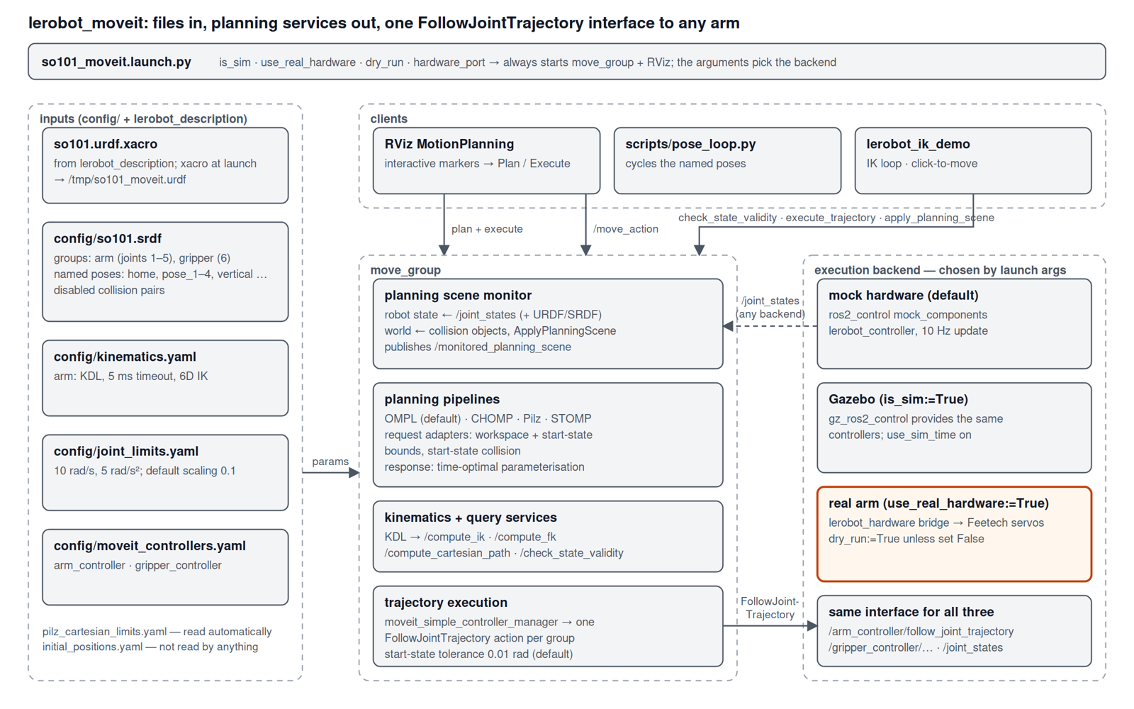
move_group, which drives any arm through one FollowJointTrajectory interface.Goal
Given the six joint angles of the SO-101, compute the pose of the gripper, and confirm the result against MoveIt's own forward-kinematics service.
What we built
- A URDF description of the arm (from the SO-ARM100 design), visualised in RViz with joint sliders so a joint can be moved by hand and the TF tree watched updating.
- A ros2_control setup with mock hardware, so MoveIt can be tried without the real arm.
- A MoveIt 2 configuration with named poses (
home,pose_1topose_4,vertical,vertical_down) and a script that cycles through them. - A hand derivation of the forward kinematics, with a script that reproduces every number.
The mathematics
Each joint has a fixed origin transform from the URDF and rotates about its own z axis, so the pose of link i is one matrix product per joint:
T_i = T_(i-1) · T_origin,i · Rz(q_i), T_0 = IThe gripper frame is T_5. Joint 1 (pan) is vertical and joints 2 to 4 are parallel, so the position has a compact closed form in terms of the
upper arm (0.116 m), forearm (0.135 m) and wrist-to-gripper (0.061 m) lengths.
Check
For the home pose (q1..q4 = 0.01534, -0.01534, 0.23476, -0.01227 rad) the derivation gives a gripper origin of
(0.01679, −0.27230, 0.22522) m. This matches MoveIt's /compute_fk service to about 3×10⁻¹⁶ m over six poses and all six links.
Run it
git clone https://github.com/sruthihsr/LerobotFwd_InvKinematics.git
cd LerobotFwd_InvKinematics && ./setup.sh && source activate.sh

ros2 launch lerobot_description so101_display.launch.py    # RViz with joint sliders
ros2 launch lerobot_moveit so101_moveit.launch.py          # MoveIt + RViz, mock hardware
In RViz, open the MotionPlanning panel, drag the interactive marker (or choose a named pose), then press Plan and Execute. The same launch file can drive the real arm; it starts in a read-only dry-run mode and only moves the arm when it is told to.
Links
- Forward-kinematics derivationEvery intermediate number, with the script that reproduces it (
fk_calc.py). - lerobot_moveit READMELaunch arguments, named poses and modes.
- MoveIt architectureHow the pieces connect.
- MoveIt 2 documentationThe motion-planning framework.
- ROS 2 Jazzy documentationThe ROS 2 release we used.
Experiment 4 of 5
Inverse kinematics with obstacle avoidance: sim to real
The gripper loops around and over a cylinder, first on a simulated arm and then on the real one.
Git repository
- LerobotFwd_InvKinematicsThe
lerobot_ik_demopackage holds the loop, the IK solver and the hardware bring-up guide.
Videos
Photos and diagrams
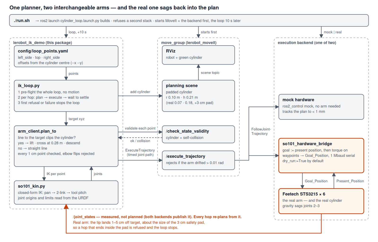
move_group. Mock hardware and the real Feetech arm sit behind the same FollowJointTrajectory interface. The orange path is what makes sim to real different: the real arm sags, so every hop is planned from the measured pose.Goal
Move the gripper to chosen positions in space, along a path that never touches an obstacle, and run the same code on a simulation and on the real arm.
The task
A padded cylinder stands in front of the arm. The gripper visits three points in a loop: to the left of the cylinder, over the top of it, and to the right. When a straight line between two points would clip the cylinder, the planner lifts the gripper, crosses over at a safe height and comes back down.
Inverse kinematics
The SO-101 has five joints, so it cannot reach an arbitrary 6-D pose. The target is the gripper position (x, y, z) plus the tool pitch, and the wrist roll is left free.
That makes the solution closed form: the pan angle from the target's direction, then a two-link (upper arm and forearm) solution by the law of cosines, and finally the wrist angle from the pitch.
There are two pan solutions and two elbow solutions; those outside the joint limits are discarded.
How we checked it. Over 1,823 random poses the closed-form solution reproduces the target with a forward-kinematics error of at most 4.5 µm. On targets that were exactly reachable, MoveIt's KDL solver found 73 of 76 and 71 of 76 (from two starting poses), while the closed form found all 76.
Obstacle avoidance
- The cylinder is added to MoveIt's planning scene with a safety pad of 3 cm.
- Before any motion the whole loop is checked in a plan-only pre-flight.
- Every hop is checked point by point (every centimetre) for collisions, and elbow flips are rejected.
- The first refusal or failure stops the loop.
Sim to real
Mock hardware follows the plan to within 1 mm, so a clean simulated run says little about the real arm. On the real arm the gripper lands 1 to 5 cm away from the target because of gravity sag in joints 2 and 3, which is about the size of the 3 cm pad. Two design decisions handle this:
- Every hop re-plans from the measured joint state, not from where the previous plan expected to end.
- A hop that ends inside the pad makes the next hop be refused and the loop stops, rather than continuing towards the obstacle.
For safety the real arm starts in a dry run: it is connected read-only and only logs the commands it would send. It moves only with --live, and asks for confirmation.
Run it
cd ros2_ws/src/lerobot_ik_demo
./run.sh                    # mock arm, plan-only: nothing moves
./run.sh --execute          # mock arm, actually loops
./run.sh real               # real arm, read-only dry run
./run.sh real --live --execute --x 0.0708 --y -0.2731   # real arm MOVES
Measure the cylinder's position for your own setup before running on the real arm; the defaults are for one particular layout.
Links
- lerobot_ik_demo READMEOne-command demo and all options.
- Inverse-kinematics derivationClosed-form solution, worked examples and
ik_calc.py. - Real-arm bring-up checklistThe ordered safety steps before the arm moves.
- ArchitectureOne planner, two interchangeable arms.
Experiment 5 of 5
Teleoperation with gesture control using computer vision
Move the arm with your hand in front of a webcam.
Git repository
- SO101-Gesture-TeleoperationWebcam controller, TCP bridge, MuJoCo receiver with inverse kinematics, and the run scripts. The real-arm support is on the
feature/Jazzy-HardwareIntegrationbranch. - SO101-Gesture-Teleoperation (original)The repository where the gesture controller and the receiver were first developed.
- lerobot_mujocoThe MuJoCo simulation package used by the receiver.
Videos
Photos and diagrams
Goal
Replace the physical leader arm with a webcam. The operator's hand position sets where the gripper goes, and hand gestures switch control on and off and open and close the gripper. The pipeline was developed and tested in simulation first, and then connected to the real arm.
In the videos
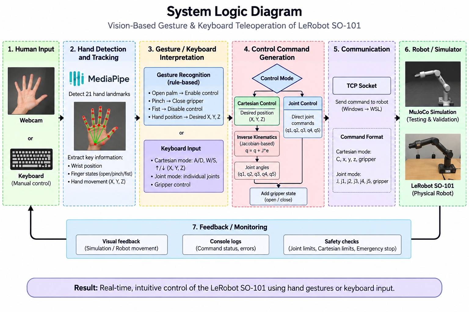
Three videos show the system at different stages: gesture control of the simulated arm alone, then the same control with the real SO-101 connected, and finally a pick-and-place task done by hand gestures. The system logic diagram below summarises the whole pipeline in seven steps.
System overview
Webcam  →  MediaPipe hand tracking  →  combined_controller.py
                                              │  TCP, one text line per command
                                              ▼
                          gesture_receiver_test.py   (inverse kinematics)
                                              │  joint positions
                              ┌───────────────┴───────────────┐
                              ▼                               ▼
                    MuJoCo SO-101 (sim)         physical SO-101 (optional)
There are two programs, so the camera side and the robot side can run on different machines. Our first setup used a Windows webcam program and the receiver in WSL (Ubuntu 22.04, ROS 2 Humble). The newer version runs both on one Ubuntu 24.04 machine (ROS 2 Jazzy), and adds the real arm.
| Part | File | Job |
|---|---|---|
| Controller | combined_controller.py | Reads the webcam, tracks the hand, recognises gestures, handles the keyboard, and sends commands. |
| Receiver | gesture_receiver_test.py | Receives commands over TCP (port 5000), solves inverse kinematics, drives MuJoCo and optionally the real arm. |
| Scene | build_scene.py | Builds the MuJoCo model of the SO-101 from the URDF and meshes. |
| Digital twin | mirror_real_arm.py | Read-only viewer that mirrors the real arm's pose from /joint_states. It never writes to the arm. |
| Run scripts | run_receiver.sh, run_controller.sh | Start each program with the right environment. |
1. Seeing the hand
The controller uses the MediaPipe Hand Landmarker model on each webcam frame, tracking one hand with a confidence threshold of 0.5. It returns 21 landmarks per hand, in image coordinates from 0 to 1. Everything below is computed from those landmarks.
2. Gestures
| Gesture | How it is detected | Effect |
|---|---|---|
| Open palm | Fingers extended | Enables gesture control and opens the gripper |
| Pinch | Thumb tip and index tip closer than 0.08 (normalised image distance) | Closes the gripper while control is enabled |
| Fist | Fingers curled | Disables gesture control |
| No hand | Nothing detected | The last target is kept |
Requiring an open palm to start means the arm does not move just because a hand walked into the picture.
3. From hand to target position
In Cartesian mode the wrist landmark gives the target in the robot's base frame, in metres:
target_x = (wrist.x - 0.5) * 0.30                    # hand left/right  -> robot x
target_y = -0.19 - (wrist.y - 0.5) * 0.26            # hand up/down     -> robot y
target_z =  0.20 + (hand_size - 0.68) * 0.60         # hand near/far    -> robot z
hand_size is the image distance from the wrist landmark to the middle fingertip. A hand closer to the camera looks bigger, so this stands in for depth, which a single webcam cannot measure directly.
The position is not set straight to the target. It moves a fraction of the way each frame, which smooths out the jitter of hand tracking:
x += (target_x - x) * (speed / 100) * 0.1 # speed defaults to 50Finally the position is clamped to a soft workspace box:
| Axis | Minimum (m) | Maximum (m) |
|---|---|---|
| x | −0.20 | 0.20 |
| y | −0.32 | −0.06 |
| z | 0.05 | 0.30 |
4. Control modes
- Cartesian mode (
C): the hand sets the gripper position, as above. Inverse kinematics finds the joint angles. - Joint mode (
J): the hand drives individual joints. For example, moving the hand left or right past a small dead zone turns the base joint. - Keyboard:
W A S Dand the arrow keys move the target,Z Xand other keys move single joints,+and-change the speed. Moving with the keyboard takes over from the gesture. PressingCorJ, or showing a fist, hands control back, and an open palm then enables gesture control again.
5. The message format
The two programs talk over a plain TCP connection. Each command is one line of text ending in a newline, so it is easy to read in a log and to test with a simple script:
| Message | Meaning |
|---|---|
C,x,y,z,g | Cartesian target in metres. g is 0 for open and 1 for closed gripper. |
J,j1,j2,j3,j4,j5,g | Five joint angles in radians, and the gripper. |
The receiver ignores a malformed line and prints a warning instead of stopping.
6. Inverse kinematics in the receiver
For each Cartesian target the receiver runs an iterative solver on a scratch copy of the MuJoCo model:
- Start from the previous joint angles.
- Read the current gripper position and the error to the target.
- Stop if the error is under 5 mm.
- Otherwise take a step of half the size that the pseudo-inverse of the Jacobian suggests (
mj_jacBodyon the jaw body, five arm joints), and clip the result to the joint limits. - Repeat, up to 12 times per command.
Starting from the last solution keeps the arm moving smoothly. The servos (or the simulated actuators) do the actual motion, so the solver only produces targets. This is different from the closed-form solver in Experiment 4, which gives an exact answer but was written for planned paths rather than a moving target.
7. Safety
- Emergency stop: Space latches a stop and R clears it.
- Limits: targets are limited to the workspace box and the joint limits above. A target outside the range the servos allow is skipped, not silently clamped.
- Dry run by default:
--real-hardwarealone connects read-only, and only logs what it would send. Moving the real arm needs--real-hardware --no-dry-run. - Safe start: when a live connection is made, each servo's goal is first set to its current position, so turning the torque on cannot make the arm jump.
- Slew limit: commands to the real servos are limited to 0.25 rad/s. The simulation moves instantly, so it leads the real arm until the log prints
startup ramp done. - Separate gripper write: the gripper is written separately from the arm, and its target is clamped to the servo's own calibrated range, which is narrower than the simulation's.
Run it
# 1. receiver first: simulation only
./run_receiver.sh
#    real arm, dry run (connects read-only, nothing moves)
./run_receiver.sh --real-hardware
#    real arm, LIVE
./run_receiver.sh --real-hardware --no-dry-run --serial-port /dev/ttyACM0

# 2. then the webcam controller
./run_controller.sh
SO101_CAMERA=1 ./run_controller.sh              # a different camera
SO101_HOST=192.168.1.50 ./run_controller.sh     # receiver on another machine
Always start the receiver before the controller. The controller needs a Python environment with MediaPipe and OpenCV (set SO101_VENV to point to it), and the hand model file hand_landmarker.task, which is in the repository.
Troubleshooting
| Problem | What to try |
|---|---|
| The MuJoCo viewer crashes on start | Run with software rendering: LIBGL_ALWAYS_SOFTWARE=1 (the run script already does this). |
| The controller cannot connect | Check that the receiver is running and listening on port 5000, and that SO101_HOST (or ROBOT_HOST in the Windows version) is the receiver's address. A WSL address changes from machine to machine. |
| “Could not open webcam” | The camera index may have changed after a USB replug. Set SO101_CAMERA to the right index or /dev/videoN. |
| The receiver does not stop on Ctrl+C | From another terminal: pkill -f gesture_receiver_test.py. |
| The real arm lags the simulation | Expected at the start: it eases toward the first target at 0.25 rad/s. |
Status and next steps
Working: hand tracking, the three gestures, keyboard control, the TCP link, inverse kinematics, MuJoCo teleoperation, an emergency stop, and dry-run and live mirroring to the real arm.
Still to do:
- Check the direction of every joint on the real arm.
- Confirm the gripper's open and closed direction (the simulation's actuator direction and the real servo's are not guaranteed to agree; confirm in dry run first).
- Replace the simulation workspace box with bounds that are safe for the physical arm.
- Test at low speed, check for collisions, and tune latency and smoothness.
Links
- Project READMESetup, how to run, keyboard controls and safety.
- MediaPipe Hand LandmarkerThe hand-tracking model.
- MuJoCoThe physics simulator.
- MuJoCo
mj_jacBodyThe Jacobian function the inverse kinematics uses. - Our post: SO-101 in MuJoCoThe simulated arm and its kinematics.
- Experiment 4: inverse kinematicsThe closed-form solver used for the obstacle loop.