
 LeRobot Experiments
Assembly · Post 1 of 6
Assembling the SO-101 and wiring it up
Leader and follower builds, a circuit diagram, and how every motor, board and camera connects.
This post covers how we built the two arms and how everything is connected. We followed the official LeRobot SO-101 assembly guide, and this page adds our own wiring diagram and notes.
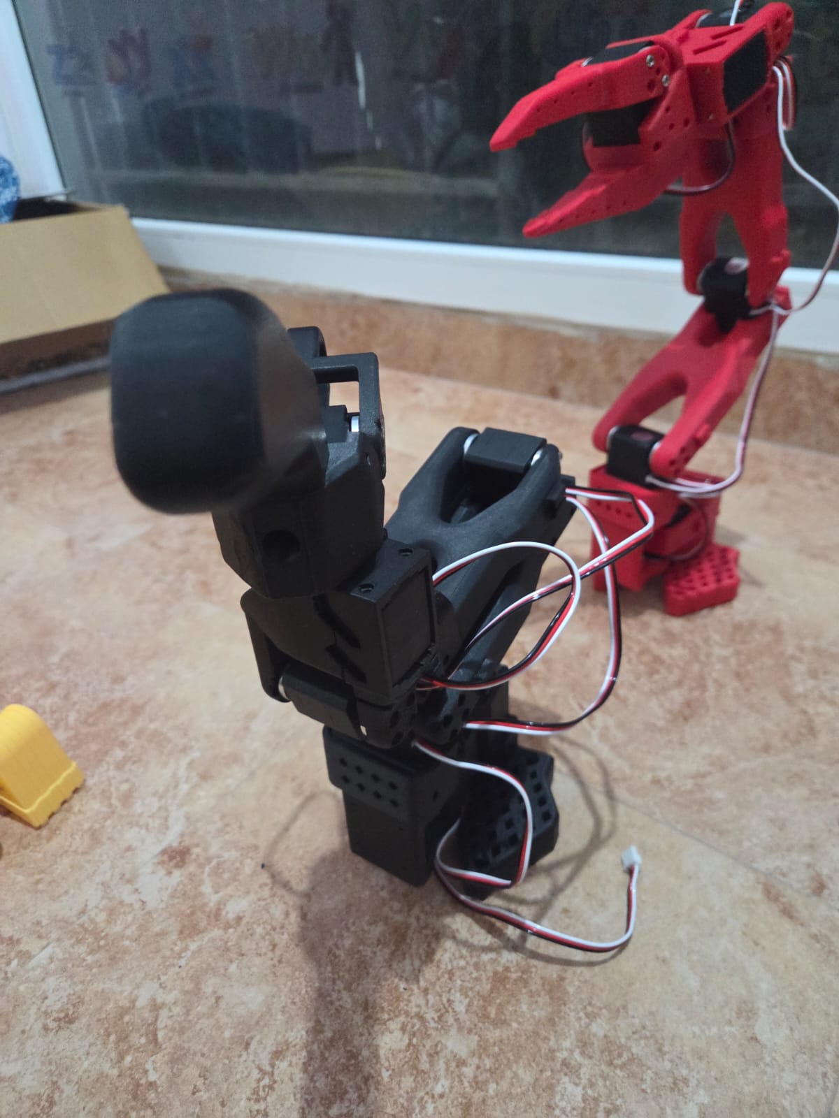
Assembly links
- SO-ARM100 hardware repoBill of materials, where to buy parts, and the 3D-print files (STL).
- LeRobot: Assemble SO-101The step-by-step guide we followed, including motor setup and calibration.
- LeRobot: InstallationEnvironment setup. The SO-101 also needs the Feetech extra:
pip install -e ".[feetech]". - LeRobot: Feetech motorsBackground on the STS3215 servos and their bus.
- Video: set motor IDsSetting IDs and baudrate one motor at a time.
- Build videos for each joint.
- Videos: follower gripper · leader handleThe only part where the two arms differ in structure.
- Video: calibrationCovered in the next post.
Parts and motors
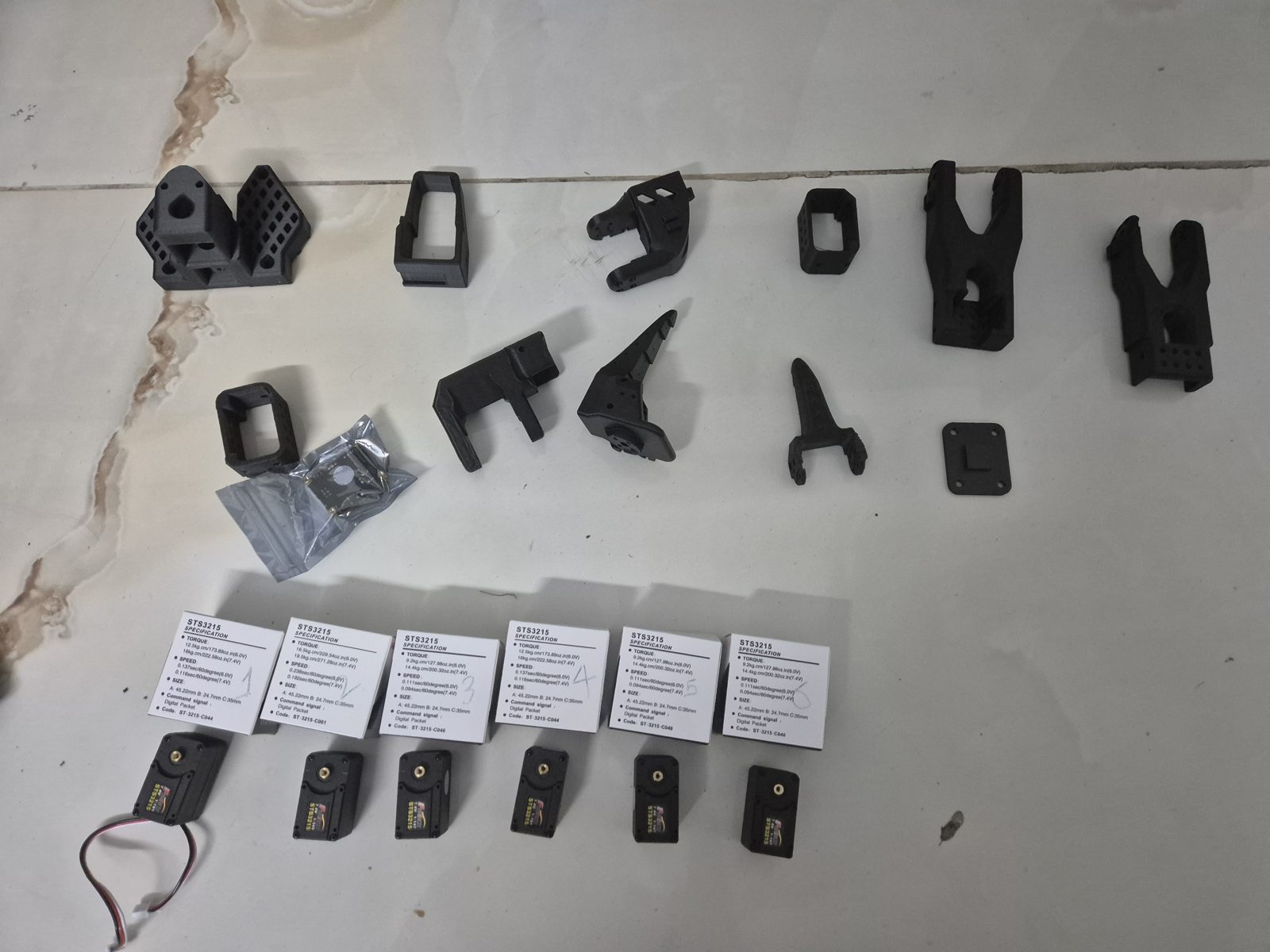
Numbering the servo boxes is worth doing. Once a motor is out of its box, the six look almost identical, and each joint needs a particular motor and a particular ID. The printed label on each box lists the torque and speed at 6.0 V and 7.4 V, and the servos are marked 7.4 V. The boxes show different torque figures, which fits the different gear ratios in the table below. Set each motor's ID while it is still on the bench (see the setup post).
Two arms, one design
Both arms have six joints and use six Feetech STS3215 servos. The follower has a gripper and every motor has a 1/345 gearbox, so it can hold its pose and carry a load. The leader has a handle with a trigger instead of a gripper, and uses three different gear ratios so it can support its own weight and still be moved by hand with little force.
| Joint | Motor ID | Follower gearing | Leader gearing |
|---|---|---|---|
| Shoulder pan (base) | 1 | 1/345 | 1/191 |
| Shoulder lift | 2 | 1/345 | 1/345 |
| Elbow flex | 3 | 1/345 | 1/191 |
| Wrist flex | 4 | 1/345 | 1/147 |
| Wrist roll | 5 | 1/345 | 1/147 |
| Gripper (trigger on the leader) | 6 | 1/345 | 1/147 |
Assembly, step by step
- Print and clean the parts. Print from the SO-ARM100 files and remove all support material with a small screwdriver. Lay everything out as in the photo above and check nothing is missing.
- Set every motor's ID first. Do this before mounting the motors. New servos all have ID 1, so each one is connected alone to the adapter and given its own ID (see the setup post). The IDs are written to the motor's memory, so this is done once.
- Fit one 3-pin cable to each motor as you place it. It is much harder to plug in once the arm is closed up.
- Build from the base upward, one joint at a time. Every joint follows the same pattern: fit the horns (a M3×6 screw in the top horn, none in the bottom one),
slide the motor into its holder, secure it with four M2×6 screws, then attach the next link with M3×6 screws.
- Joint 1 (motor 1): motor into the base, then the motor holder and the shoulder.
- Joint 2 (motor 2): motor in from the top, then the upper arm.
- Joint 3 (motor 3): motor, then the forearm.
- Joint 4 (motor 4): motor holder, then the motor.
- Joint 5 (motor 5): motor into the wrist holder, then the wrist onto motor 4.
- Gripper (motor 6): on the follower, the moving jaw and claw. On the leader, the leader holder, handle and trigger.
- Chain the cables and mount the adapter on the base, as described below.
- Find the ports and calibrate both arms.
Circuit diagram
The whole system is a computer, two identical servo adapters (one per arm), two power supplies, twelve servos, and two cameras.
How it is connected
1. Servo bus: adapter to motors
Each arm is a single daisy chain. A short 3-pin cable runs from the adapter to the motor with ID 1 (shoulder pan). From there each motor is plugged into the next one, in order, up to the gripper motor with ID 6. The three wires of each cable are ground, servo power and a single signal line. All six motors share that one signal line, which is half-duplex serial. The adapter sends a message addressed to an ID and only the motor with that ID answers. This is why every motor must have a unique ID and all of them must use the same baudrate. Because the power wire runs along the same chain, the adapter feeds all six motors.
2. Power
Each arm has its own DC power supply, plugged into its adapter. The servos draw much more current than a USB port can supply, so the arms are never powered from the computer. A motor chain cannot be powered from USB alone.
3. USB: computer to adapters
Each adapter connects to the computer by its own USB cable and appears as a serial port. On our computer the leader is /dev/ttyACM0 and the follower is
/dev/ttyACM1. Use lerobot-find-port to check which is which, because the numbers depend on which cable was plugged in first. If you use a Waveshare adapter, set both of its jumpers to
channel B (USB).
4. USB: computer to cameras
The two cameras connect straight to the computer and show up as video devices: the top camera as /dev/video2 and the wrist camera as /dev/video4.
Connection summary
| From | To | Link | Carries |
|---|---|---|---|
| Computer | Leader adapter | USB (/dev/ttyACM0) | Commands and joint readings |
| Computer | Follower adapter | USB (/dev/ttyACM1) | Commands and joint readings |
| Power supply (leader) | Leader adapter | DC power input | Servo power |
| Power supply (follower) | Follower adapter | DC power input | Servo power |
| Each adapter | Motor ID 1, then 1→2→…→6 | 3-pin cable | Power, ground, half-duplex data |
| Computer | Top camera | USB (/dev/video2) | 640×480 video at 30 fps |
| Computer | Wrist camera | USB (/dev/video4) | 640×480 video at 15 fps |
Common pitfalls
- Loose cables during ID setup. If the power lead drops out while you handle the board, the motor stops answering and the script fails. Check the cabling before pressing Enter.
- More than one motor on the bus while setting IDs. Two motors with ID 1 answer at once and corrupt each other's replies. Connect only one motor at a time.
- A broken chain. If one motor is unplugged, every motor after it in the chain disappears. When the arm reports missing motors, check the cable just before the first missing ID.
- Swapped arms. It is easy to confuse which port is the leader and which the follower. Label the two USB cables.
Once assembled and wired, continue to setting up and calibrating the arms. To see what we did with the finished arms, go to the experiments.